Introduction
The Nu Plasma is a state of the art multiple collector ICP mass spectrometer. Featuring a double focusing Nier Johnson design in which the energy spread of theion beam is compensated for to produce a high quality image. The massspectrometer comprises an electrostatic analyser (ESA) followed by a magnetic sector.The various beams, which are separated by mass using the magnet, are focussed onto a Faraday detector array. Between the magnet and this array are placed two lens arrays (in the form of a series of plates above and below the ion beam path) that can act as a zoom lens to alter the dispersion of the instrument removing the necessity for moveable collectors.
As an ion beam passes through a magnetic field it is deflected, the amount of deflection depends upon the ion energy, the mass of the ion and ion charge. A conventional sector magnet also focuses the ion beam in the plane of the deflection, such that an image of a narrow source slit can be produced in such a simple mass spectrometer without any extra electrostatic lens elements. This is the basis of simple single focussing mass spectrometers, but this simple design suffers from the problem that if any energy spread is present in the beam, a resulting blurring of the image occurs. This is due to the magnetic deflection being energy, as well as mass dependent. It can also be shown that if the pole angle of the magnet is offset from being normal to the ion beam path, focusing in the vertical plane can also be achieved.
To overcome the blurring due to ion energy spread, a second electrostatic analyser ESA is combined with the magnet. The deflection from the ESA depends solely on the ion energy (i.e. is mass independent) and the radius and position of this ESA can be chosen such that the displacement due to the ion energy spread after passing through the ESA exactly compensates for the displacement produced by the magnet. Such an arrangement is termed "Double Focusing" and is the approach adopted for all high-resolution magnetic mass spectrometers.
Samples are introduced into the plasma source from a number of different preparation systems including auto sampler and Laser Ablation accessories. The sample is transported in an argon gas stream into the central channel of the torch where it is ionised by energy transfer with the argon Plasma to atomise and ionise the sample.The ions are then transported through the instrument-sampling cone into a region evacuated using a rotary pump where they experience supersonic expansion. Most of the sample is transported through this primary cone. A second cone (skimmer) then samples some of this plume; this provides the primary source for transfer via the extraction and transfer optics into the mass spectrometer. For a full description of the processes involved in this type of source, one of the many textbooks on ICPMS should be referred to.
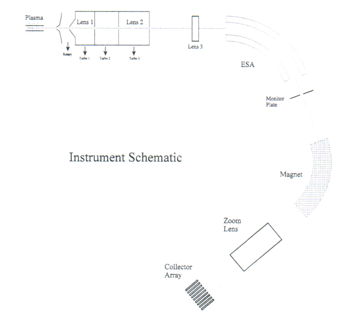
A high vacuum pneumatic isolation valve preserves the vacuum integrity of the mass spectrometer. Within the housing at the front of the ESA is a lens stack, which serves two purposes; The first defines the acceptance angle of the ion beam that can pass through the complete instrument using a rectangular aperture (approximately) 4mm high x 8mm wide. These dimensions have been carefully calculated to maximise the transmission whilst ensuring that the peak-shape suffers from as little distortion caused by aberrations as possible. These off axis beams normally dominate such aberrations. Following this aperture a series of plates permit the deflection of the ion beam in the vertical plane. Also provided, a simple Einzel electrostatic lens to focus the beam in the vertical plane and so maximising the transmission through the magnet region.
At the ESA exit an intermediate image of the source slit is produced, due to the focussing properties of the ESA itself (i.e. this focussing is independent of any other lens elements). A slit has been placed, which connected to a preamplifier permits the monitoring of the beau as it passes. This facility has been provided to aid optimisation, and ensure the beam passes through the centre of the slit.
At the entrance to the flight tube, just before the magnet region, a second aperture is used with dimensions 4mm high X approximately 25mm wide. The purpose of this aperture is to ensure that beam can't hit the top and bottom surfaces of the flight tube. If this occurred the transmission of the various isotopes through the instrument could vary depending upon their flight path, would produce an apparent mass bias. The exit pole of the magnet is at approximately 27?to the ion beam path. This has two effects; it increases the image plane distance over that which would result from a normal incidence pole, and hence increases the dispersion of the instrument, and it produces a focussing in the vertical plane, this focussing combined with the focussing from the electrostatic lens in front of the ESA produces a vertical image of the source slit in the collector region. The position of this vertical focus is chosen to lie beyond the horizontal focus (as defined by the slit plate of the Faraday assembly) so as to ensure full transmission into the ion counting detectors.
Following the magnet are the two zoom lens assemblies. These are designed to producequadrupolar fields (i.e. they emulate the field produced by simple quadrupole rod assemblies). However the use of normal rod systems has not been pursued (or evencontemplated) since the large aperture required for these elements would result in largeaberrations on the ion beam if such conventional design were employed. The use of an array of plates above and below the ion beam path on which a series of quadratically increasing voltages are applied however matches the required field exactly, whilstminimises any aberrations due to extensive fringe fields.
The separation between adjacent masses at the collector is given by the formula:
Separation (mm) = Dispersion (mm) / Average mass (amu)
The dispersion of an instrument is normally fixed, and as an example of the formula we will consider an instrument with a dispersion of 500mm. Thus at mass 240 the separation between two adjacent isotopes at the collector array is (500/240) i.e. approximately 2.1mm If one was to study two isotopes at a mass of 150 amu'the separation increases to(500/150) i.e.3.3mm. Since the dispersion is normally constant for such instruments it has become conventional to mount the individual detectors on movable assemblies so as.to match this variation in beam position with mass.
The provision of the two quadrupole lenses which together act as a zoom lens, (similar to a zoom lens on a camera) can alter the image magnification at the detector array, which means that, the dispersion is no longer a constant term.

Firstly exact coincidence with every third collector is assumed without any required“assistance” from the zoom lens. In the second example the zoom lens is activated to produce a demagmfication of 2/3 so that the beams are now coincident with every second collector. Although the user may just utilise a lookup table to find the settings required tor any particular element, it is perhaps worthwhile in having some feel for the process involved.
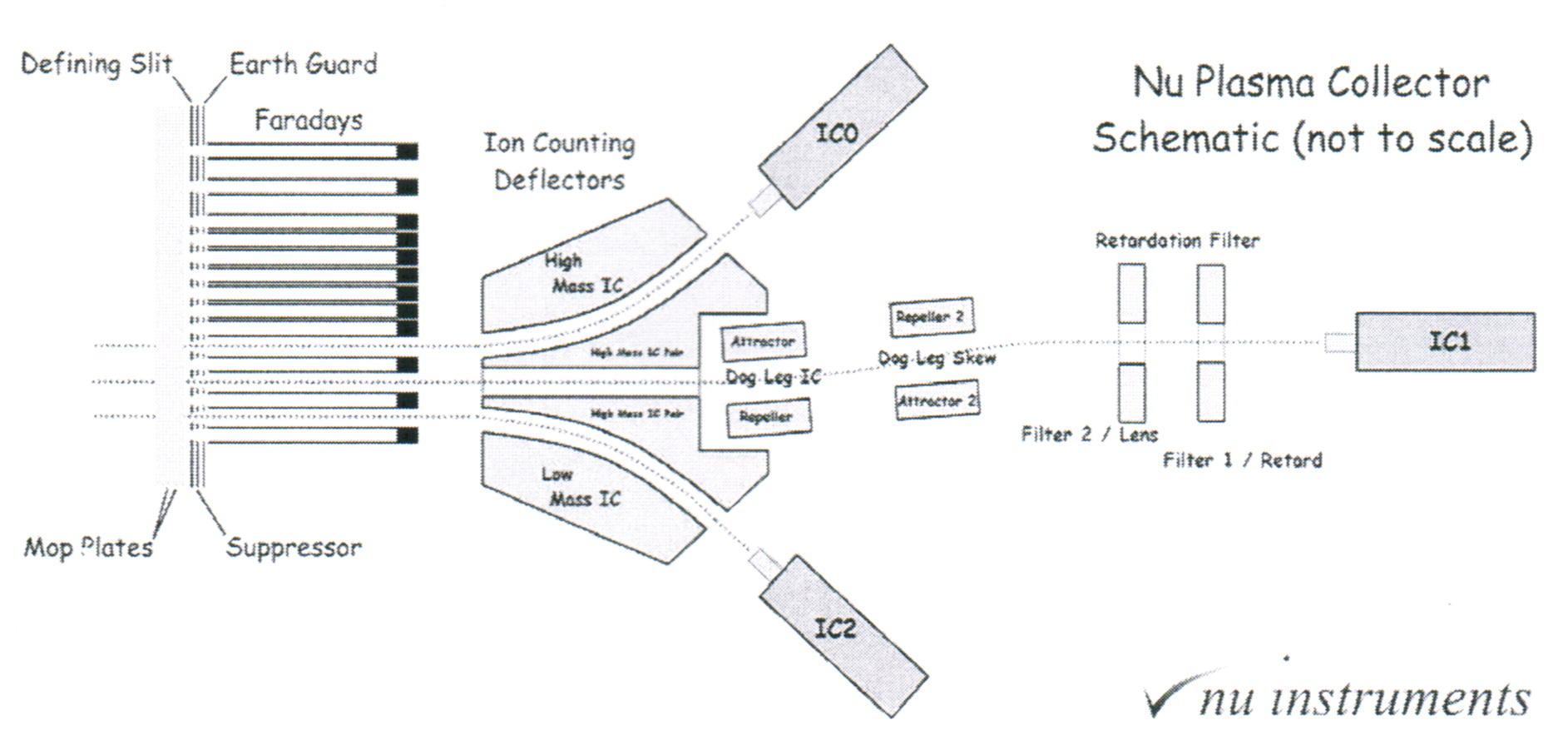
We have adopted the convention to label the collectors from H6 to L5 through AX, 12 in total.
To define a mass scale for the instrument, one requires a reference point. Faraday AX is the centre line and as such is the collector that defines the mass scale in all work.
The slits for the three ion counting channels (ICO, IC1 and IC2) lie on the low mass side between the last four Faraday collectors.
A small double ESA assembly that deflects the two outer ion beams into off axes ETP multipliers follows the Ion counting channels. The central beam passes through a slot in the central block. There is a small deflection imposed onto the ion beam to ensure that the multiplier does not lie directly in line with its central channel. This is done to permit the beam to be deflected if an intense signal is observed (one can also deflect the beam using the main ESA assembly) and also allows one the possibility of ensuring that the centre of the multiplier coincides with the beam. The same effect is achieved with the off-axes multipliers by slightly altering the deflection ESA voltages. A high abundance filter can also be used to permit high abundance sensitivity studies (If required).
Main Technical Specifications
1 . Resolution
RP = M/ΔM = 400 (10%Height)
2. Signal Sensitivity
|
Element |
Sensitivity in Vol./ppm |
Seneitivity in cps/ppm |
|
Li |
4 |
2.5x10⁸ |
|
Sr |
8 |
5.0x10⁸ |
|
Nd |
10 |
6.3x10⁸ |
|
Pb |
15 |
9.4x10⁸ |
|
U |
20 |
1.3x10⁹ |
3. Abundance sensitivity
Tail contribution at 237 amu from 238 amu peak is 5ppm
4. Accuracy and Precision
|
Isotopic Ratio |
Precision(‰) |
Isotope Ratio Specifications (ppm) |
|
Internal |
External |
Internal |
External |
Normalization to |
|
207Pb/206Pb |
<0.01 |
<0.03 |
20 |
20 |
205Tl/203Tl = 2.3875 |
|
143Nd/144Nd |
<0.01 |
<0.03 |
20 |
20 |
146Nd/144Nd=0.7219 |
|
87Sr/86Sr |
<0.01 |
<0.03 |
20 |
25 |
86Sr/88Sr = 0.1194 |
|
176Hf/177Hf |
<0.01 |
<0.03 |
20 |
20 |
179Hf/177Hf=0.7325 |
5. RF Power
2000W
6 Laser Ablation System
Nd:YAG Laser: 213nm
Laser Spot Size: 5~160μm
Manufactured from New Wave Research, Inc.
linkman: Dr. zhaozhiqi email: zhaozhiqi@mails.gyig.ac.cn
|